Instructions For Use
Part No.: 01-1020-IB-Stim
Den180057
K241533
K250451
Rx Only
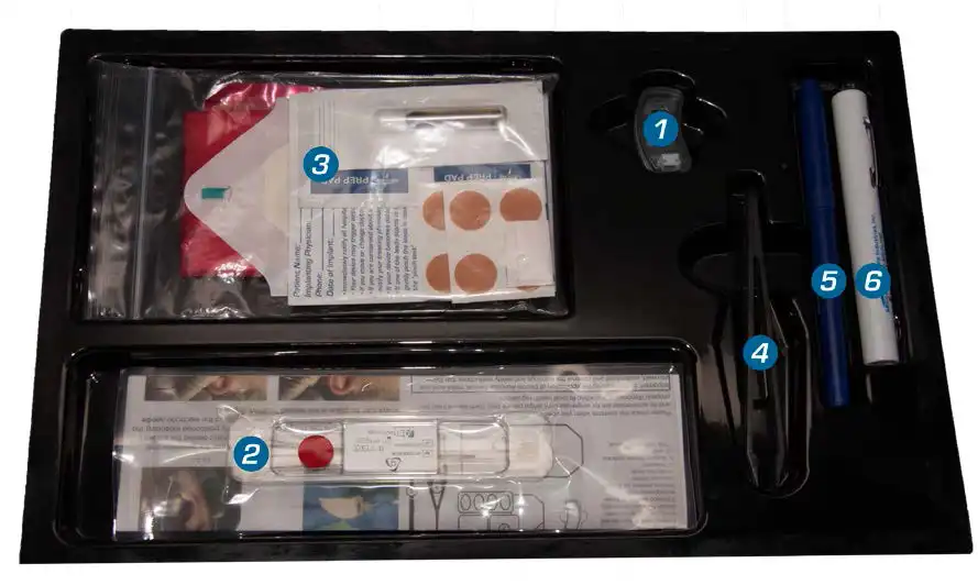
Items supplied in the kit:
- 1
IB-Stim stimulator with inserted but not activated batteries
- 2
Sterile Wire Harness for use with IB-Stim stimulator only
- 3
Round Bandages to fasten the appliance leads, Stimulator adhesive, SkinTac™, Alcohol swab, Transparent Dressing, Bio-Hazard Bag and Patient ID Card
- 4
Tweezers
- 5Surgical Marker
- 6
Transilluminator
- 7
This instruction manual
Please check the contents when you open the package. The IB-Stim stimulator and its accessories are for single-use only, single patient only. Each device must be properly disposed of according to local health regulations.
Indications for Use
The IB-Stim is a percutaneous electrical nerve field stimulator (PENFS) system intended to be used in patients 8-21 years of age with functional abdominal pain associated with irritable bowel syndrome (IBS) and functional dyspepsia (FD). The IB-Stim is intended to be used for 120 hours per week, using 1 device per week for 4 consecutive weeks, through application to branches of Cranial Nerves V, VII, IX and X, and the occipital nerves identified by transillumination, as an aid in the reduction of pain when combined with other therapies for IBS and FD.
FD patients for whom IB-Stim is indicated have also been shown to experience reduction of nausea symptoms.
Recommended Treatment
In the original RCT, changes in stooling frequency during treatment with IB-Stim were not formally evaluated. The largest effect on all pain measures, including composite pain scores and worst pain, was seen after completing 3 consecutive weeks of treatment. A fourth consecutive week of treatment was included in clinical testing; no safety concerns were identified with this extra consecutive week of treatment, but efficacy was not evaluated at the 4-week time point.
In published studies done after the RCT, systematic literature review did not identify safety or effectiveness concerns with changes to the age range. Recommendation from the North American Society for Pediatric Gastroenterology, Hepatology and Nutrition (NASPGHAN) based on clinical literature and current practice of medicine support the 4-week treatment. In addition, clinical literature supports safe and effective use of the IB-Stim device in children as young as 8 years old. Recommended treatment protocols are for 1 device per week for 4 consecutive weeks.
Patients should be encouraged to make lifestyle modification during treatment. Long-term treatment options with psychological or pharmacological interventions should also be discussed with patient prior to, or at the time of initiating therapy with IB-Stim.
About The IB-Stim Stimulator
IB-Stim stimulator is a battery-operated micro-stimulation appliance weighing 5 grams designed as a disposable product for a single use. IB-Stim stimulator is placed behind the patient’s ear and connected to stimulation needles on the auricle. IB-Stim stimulator offers regular therapy over several days. The appliance transmits low-frequency electric pulses.
Contraindications
A healthy, clean, intact skin surface is essential for the use of IB-Stim stimulator.
Warnings & Precautions
Procedure For Placement of the IB-Stim Stimulator
These instructions are to be used in conjunction with the training program designed to familiarize the clinician with the clinical features of the IB-Stim stimulator and how to use it in a safe and effective manner.

Fig. 1
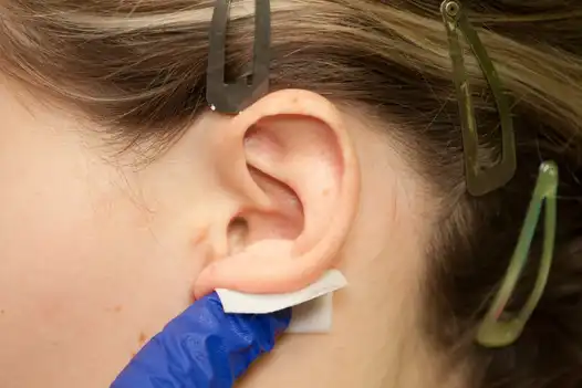
Fig. 2
Clean off the anterior (ventral) and posterior (dorsal) of the outer ear with an alcohol pad to remove all surface oils, make up and disinfect the skin. Next use Skin-Tac™ wipe on zones of ear where leads will be implanted and behind ear where the stimulator is placed. (Fig. 1, 2
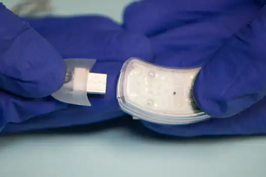
Fig. 3.1
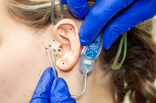
Fig. 3.2
To activate the IB-Stim stimulator, the wire harness is inserted into the stimulator until firmly seated.(Fig. 3.1) Temporarily place the stimulator behind the patient’s ear. Carefully observe that the stimulator is properly positioned extending the harness wires over the ear allowing enough length so the electrode needles can be placed at the desired location. (Fig. 3.2) Marking implantation site with the provided surgical marker is optional.
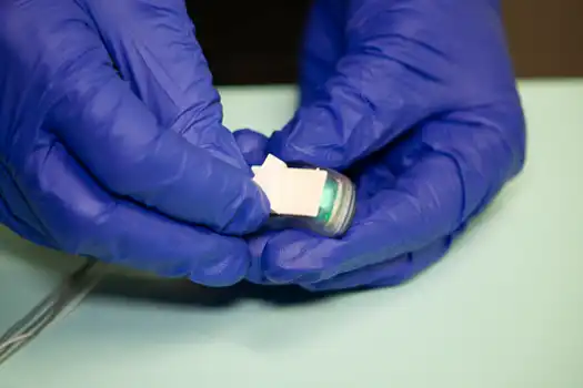
Fig. 4
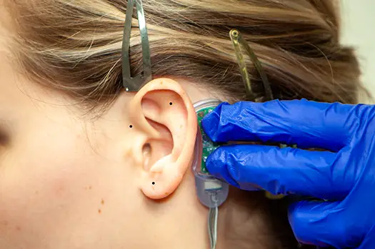
Fig. 5
Remove the protective coating on the adhesive strip on the back of the IB-Stim stimulator (Fig. 4). Gently press the stimulator onto the skin posterior to the external ear (Fig. 5).
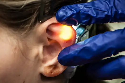
Fig. 6
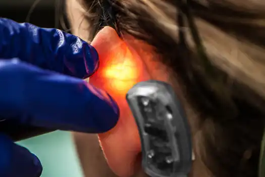
Fig. 7
The correct location for implantation of the electrode needles is determined by cranial and occipital neurovascular bundles visualized by transillumination (Fig. 6, 7). *Detailed explanation of transillumination located below.
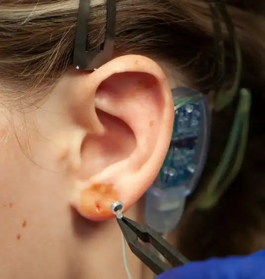
Fig. 8
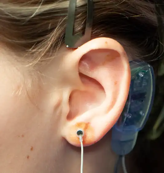
Fig. 9
Stimulation can be accomplished by ventral (anterior) and/or dorsal (posterior) percutaneous implantation of the electrode needles. Once the desired neurovascular bundles are visualized by transillumination, the electrode needle is secured by the provided tweezers and implanted percutaneously with gentle pressure. The four needle electrode array, attached to the white wire, is placed on the ventral (outer) side of the ear lobe as determined by transillumination (Fig. 8, 9).
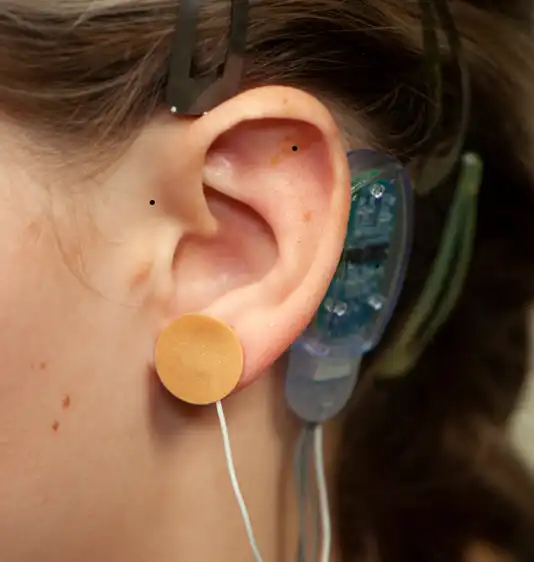
Fig. 10
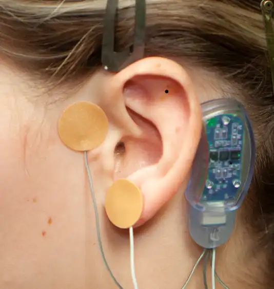
Fig. 11
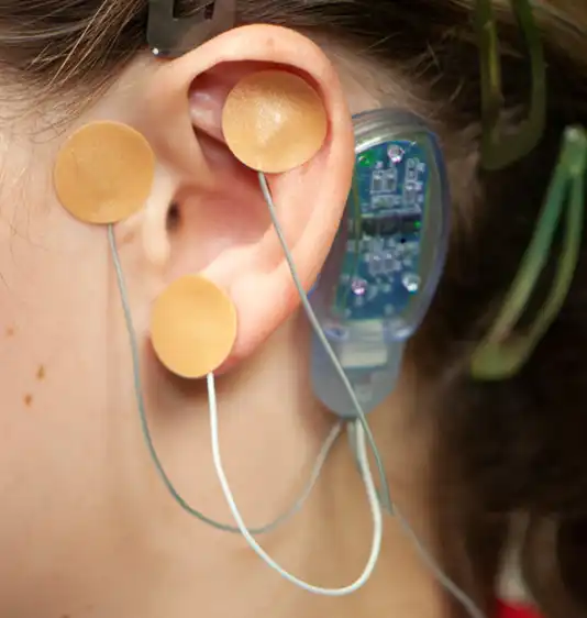
Fig. 12
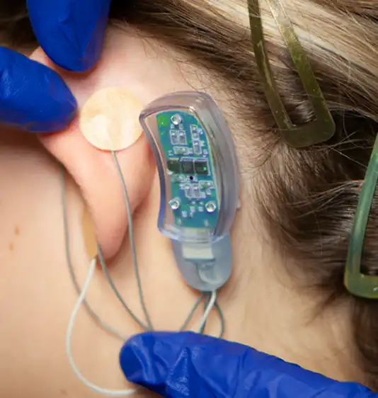
Fig. 13
A provided round bandage is then placed over the implanted electrode needle array and gently secured to prevent electrode needle array migration. The procedure is then repeated for implantation of the second electrode needle, the third electrode needle and the fourth and final electrode needle (Fig. 10, 11, 12, 13).
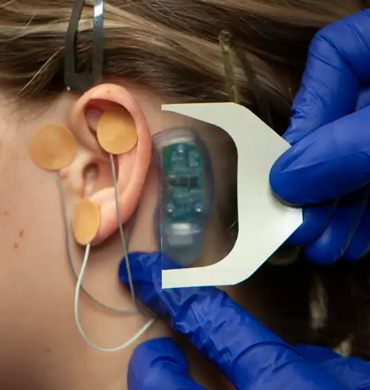
Fig. 14
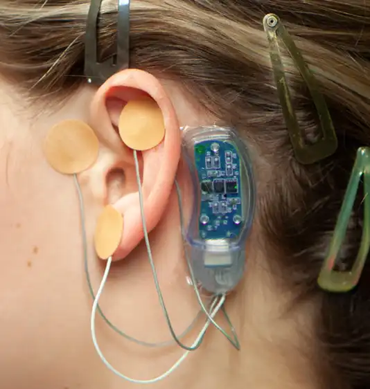
Fig. 15
The supplied Tegaderm™ strip is then placed over the stimulator to help avoid component migration (Fig. 14). The application of the IB-Stim device is now complete (Fig. 15). Have your patient return to the office in 5 days. Carefully and safely remove the device with appropriate instrumentation following blood hazard protocols. Place the device into the Bio-Hazard Bag, contained in the surgical kit. Clean the patients ear area. Dispose of the bag as medical waste, following your appropriate state regulations.
Transillumination
The correct location for implantation of the electrode needles is determined by cranial and occipital neurovascular bundles visualized by transillumination. Use of the transillumination technique will help ensure the IB-Stim stimulator will be implanted safely and effectively for all indicated patients.
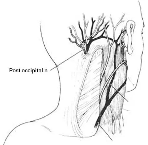
Fig. 16
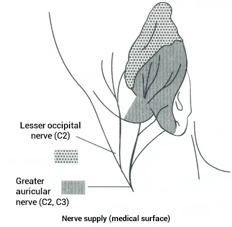
Fig. 17
The external ear contains peripheral branches of cranial nerves V, VII, IX, X as well as peripheral branches of the occipital nerves (Fig. 16, 17).
Auricular Innervation
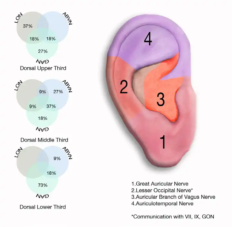
Fig. 18
These neurovascular bundles are located in predictable areas (referred to as zones) with predominant, predictable concentrations of cranial and occipital neurovascular bundles (Fig. 18).

Fig. 6

Fig. 7
These neurovascular bundles can be visualized by transillumination on the ventral (Fig. 6) and the dorsal (Fig. 7) aspect of the external ear. This is accomplished by placing the transilluminator tip against the skin and viewing the opposite side of the external ear as light passes through the tissue. The neurovascular bundles will be outlined due to anatomical variance and the difference in tissue density. Marking the desired implantation site with the provided surgical marker is optional.
The location of the implantation site of the electrode needles must be within 0.5 – 2mm of a neurovascular bundle to avoid bleeding and discomfort. If bleeding and discomfort occurs, reevaluate placement location with transillumination and reposition the leads.
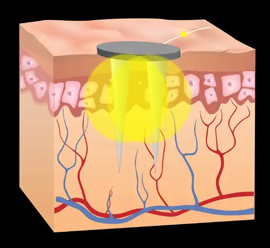
Fig. 19
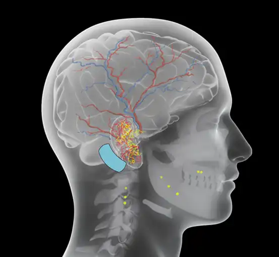
Fig. 20
Accurate percutaneous implantation of the electrode needles will create a zone of electrical stimulation which will encompass branches of the cranial and occipital nerves, arterial branches (both indirectly and transarterial), and the co-joined neurovascular bundles (Fig. 19, 20).
Preclinical Summary
The ability of the IB-STIM to produce systemic effects by modulating branches of cranial nerves V, VII, IX and X has been demonstrated in preclinical animal models.
Clinical Summary
The overall study was a double blind, randomized, sham-controlled study that included a cohort of patients (n=104), ages 11-18 years with functional abdominal pain disorders (FAPDs) based on Rome III criteria and included subjects with irritable bowel syndrome (IBS), functional abdominal pain, functional dyspepsia and abdominal migraine. The study was designed to measure the effects of IB-Stim compared to sham on several aspects of pain including worst pain and the pain frequency severity duration (PFSD) composite score. Other outcomes measured were global symptom improvement based on the Symptom Response Scale (SRS). A post-hoc analysis of ≥ 30% improvement in worst or usual abdominal pain was also done.
In all subjects, application of IB-Stim or sham device was weekly for a total of 4 weeks and efficacy data were collected after 1, 2 and 3 full weeks. “Weekly” treatment refers to 5 days of active or sham stimulation (as dictated by device battery life) and a 2-day rest period with the device to be removed prior to the next application.
A post-hoc sub-group analysis in a total of 50 subjects focused on reduction of abdominal pain in subjects with irritable bowel syndrome (IBS-D, IBS-M and IBS-C). Below data from the IBS subgroup analysis are presented. For additional information on the clinical study, please see the article published by Kovacic et al. (2017).
Kovacic K, Hainsworth K, Sood M, Chelimsky G, Unteutsch R, Nugent M, Simpson P, Miranda A. Neurostimulation for abdominal pain-related functional gastrointestinal disorders in adolescents: a randomised, double-blind sham-controlled trial. Lancet Gastroenterol Hepatol. 2017;2:727-737.
Pain Outcomes
In the IBS sub-group, greater improvement in worst pain (shown as mean ±SEM) was found from baseline at week 1 (1.47±0.63) and week 3 (2.38±0.63) in the IB-Stim group compared to sham. Similarly, improvements were seen in composite pain scores at week 1 (7.91±3.99) week 2 (8.07±4.02) and week 3 (11.53±3.99) compared to sham. Overall, there was a gradual improvement in pain over time in subject treated with active IB-Stim with the largest effects seen at week 3.
Between group differences in composite pain scores noted after 3 weeks showed that the IB-Stim group had improvement in worst pain and PFSD composite scores compared to sham. The IB-Stim group had a lower composite pain score (7.5; IQR 3.6-14.4) compared to sham (14.4; 4.5-39.2). Similar results were seen in worst abdominal pain scores. The IB-Stim group had a lower worst pain score (5.0; IQR 4.0-7.0) compared to sham (7.0; 5.0-9.0).
IB-Stim treatment resulted in at least a 30% decrease in worst pain at the end of 3 weeks in 59%(16/27) vs 26% (6/23) in the active and sham groups, respectively.
Clinical Data
In published studies done after the original RCT, a systematic literature review did not identify safety or effectiveness concerns with these changes. Recommendation from the North American Society for Pediatric Gastroenterology, Hepatology and Nutrition (NASPGHAN) based on clinical literature and current practice of medicine support the 4-week treatment. In addition, clinical literature supports safe and effective use of the IB-Stim device in children as young as 8 years old.
A post-hoc analysis of a study was conducted in 23 subjects who met Rome III criteria for FD. Data from those 23 subjects were extracted from a prospective study that enrolled 115 adolescents with pain-associated DGBIs recruited from a tertiary care pediatric gastroenterology clinic. The treatment arm subjects were treated with IB- Stim and control arm subjects had a sham device. At extended follow-up (8-12 weeks after the end of treatment), 7 of 13 subjects treated with active IB-Stim continued to have at least a 30% reduction in abdominal pain compared to zero of 10 subjects receiving sham treatment, consistent with the results observed in the general study population of adolescents with pain associated DGBIs. Additionally, FD patients reported reduced nausea symptoms when comparing the IB-Stim and sham group at extended follow-up. Given the limitations of a post-hoc analysis in a small subgroup of FD subjects, real world evidence including clinical literature supports these findings.
In addition, no serious adverse events were reported for these patients. Recommendations from the North American Society for Pediatric Gastroenterology, Hepatology and Nutrition (NASPGHAN) based on clinical literature and current practice of medicine support use of PENFS for functional abdominal pain.
Risks
No safety data exists in adolescents with IBS treated longer than 4 weeks. Reported side-effects were similar between groups. There were no serious adverse events reported with active treatment. Overall, 10/104 (9.6%) of patients reported side-effects which included mild ear discomfort (n=6; three in the active stimulation group, three in the sham group), adhesive allergy (n=3; one in the IB-Stim group, two in the sham group), and syncope due to needle phobia (n=1; in the sham group).
Global Symptoms Improvement
The SRS was used to measure global symptom improvement as a secondary outcome. This scale was used to assess within-patient change over time as better, worse, or no change based on a 15-point scale across individual domains for both improvement and deterioration of overall symptoms. A global symptom rating on the symptom response scale (SRS) of +2 was considered clinically significant improvement in overall symptoms.
An improvement in the treatment group over sham was seen after 3 weeks of treatment. At the end of 3 weeks of therapy, 81%(22/27) of the IB-Stim compared to 26% (6/23) of the sham group reported overall symptom improvement with an SRS score of ≥2.
Changes in stooling frequency during treatment with IB-Stim were not formally evaluated.
Returned Devices
Returned devices must be carefully cleaned and then returned in the original packaging. lf the original packaging is no longer available the device must be suitably packaged for the method of shipping chosen.
Operation / Transport / Storage
Recommend no prolonged storage / exposure outside the recommended ranges for operation, transport and storage:
Temperature: 22 °C +/- 5 °C
Relative Humidity: 20 – 80 %
The product has a limited shelf life. Details are printed on peel off label located on front of kit. Values higher or lower than the ranges specified above will shorten the useful life of the device or may cause certain components to be destroyed.
Company Contact
NeurAxis, Inc.
Carmel, IN 46032
Phone: 812-689-0791
Email: info@neuraxis.com
Contract Manufacturer
GMI Corporation
700 International Drive.
Franklin, IN 46131
Manufacturer Liability
The manufacturer and supplier of the device will not accept any liability in the following cases:
- If the device is not used in accordance with the instructions for use.
- If the operator is inadequately qualified or is not sufficiently informed about the functioning of the device on the basis of the instructions for use and the
safety instructions. - If any defects are discovered when the contents of the package are examined, the complete unit including all components must be returned as described in section “Returned Devices” to the manufacturer or the manufacturer’s local representatives.
Warranty Conditions
The manufacturer guarantees the product for the period up to the expiration date printed on the peel off label located on front of kit, or 12 months from date of purchase, whichever comes first. This guarantee applies to flaws of material and workmanship. Claims are only accepted under the following terms: The manufacturer and/or supplier is informed immediately of the fault for which the warranty claim is being made. The instructions of the manufacturer and/or supplier on storage or return of the device are within compliance. Presentation of a legible copy of the invoice for that particular device, showing the date of purchase. An exact description by the customer of the defect or fault identified.
IMPORTANT: The manufacturer’s warranty will be void if it is found that the device was damaged by force, operator error, or that it was used in any way contrary to the instructions for use and the safety instructions. If the manufacturer is required to meet a warranty claim in accordance with these terms, the customer shall bear the cost and risk of transporting the device to and from the place of use. The manufacturer and/or supplier under no circumstances assumes liability for ordinary negligence. Claims for compensation for loss of earnings and profits will likewise not be accepted.
EMC Labeling
The IB-Stim is a DC powered medical device that operates normally in almost all conditions and no reports have been received by the manufacturer or the distributor of any malfunctions due from exposure to electro-magnetic, RF, RFID or any other electrical environments. IB-STIM is suitable for use in all establishments, including domestic establishments and those directly connected to the public low-voltage power supply network. Exposure to extreme magnetic or electrical fields, such as RF, diathermy, electrocautery, RFID and security systems (e.g., environments such as MRI scanner rooms, surgical suites or anywhere
electromagnetic fields exceed the tested levels in Tables 3, 4 and 5 ) may interfere with your devices operations. Any interference should be temporary and cease immediately upon exiting the extreme environment. Some of the RF emitters might not be visible and the device can be exposed to fields from these RF emitters without the user’s awareness. We suggest you avoid prolonged exposure to these areas. If you suspect the device is not functioning properly, contact your provider, or via the company / manufacturer contact listed on this page.
The IB-Stim was tested according to:
IEC 60601-1-2
Medical Electrical Equipment
Part 1: General Requirements for Safety
2. Collateral Standard Electromagnetic Compatibility Requirements and Tests
Using:
CISPR 11: 2009, A1:2010
Class B, Group 1
Industrial, Scientific and Medical (ISM) Radio-Frequency Equipment
Electromagnetic Disturbance Characteristics
Limits and Methods of Measurement.
It was found that the IB-Stim met the above test specifications. The Power Line Conducted emissions test was not performed, or required, because the EUT is powered from a D.C. power source. It does not have line cord to plug into the A.C. power line.
Electromagnetic Emissions Testing
| Guidance and manufacturer’s declaration – electromagnetic emissions | ||
|---|---|---|
| The IB-STIM is intended for use in the electromagnetic environment specified below. The customer or the user of the IB-STIM should assure that it is used in such an environment. | ||
| Emissions test | Compliance | Electromagnetic environment- guidance |
| RF emissions CISPR 11 | Group | The I8-STIM uses RF energy only for its internal function. Therefore, its RF emissions are very low and are not likely to cause any interference in nearby electronic equipment. |
| RF emissions CISPR 11 | Class B | – |
| Harmonic emissions IEC 61000-3-2 | Not applicable DC Powered |
– |
| Voltage fluctuations/flicker emissions IEC 61000-3-3 | Not applicable. DC Powered | – |
| – | [See 5.2.2.1 c and Figure 1] DC Powered | The I8-STIM is suitable for use in all establishments, including domestic establishments and those directly connected to the public low-voltage power supply network that supplies buildings used for domestic purposes. |
| RF emissions CISPR 14-1 | Column 2 Value 8 | The IB-STIM is not suitable for interconnection with other equipment. |
| RF emissions CISPR 15 | Column 2 Value 9 | The IB-STIM is not suitable for interconnection with other equipment. |
Immunity Testing
| Guidance and manufacturer’s declaration – electromagnetic immunity | |||
|---|---|---|---|
| The 1B-STIM is intended for use in the electromagnetic environment specified below. The customer or user of the IB-STIM should assure that it is used in such an environment. |
|||
| IMMUNITY test | IEC 60601 Test Level | Compliance Level | Electromagnetic environment- guidance |
| Electrostatic discharge (ESD)
IEC 61000-4-2 |
± 6 kV contact
±B kV air |
– | Floors should be wood, concrete or ceramic tile. If floors are covered with synthetic material, the relative humidity should be at least 30 %. |
| Electrical fast transient/burst
IEC 61000-4-4 |
± 2 kV for power supply lines
± 1 kV for input/output |
– | Mains power quality should be that of a typical commercial or hospital environment. |
| Surge
IEC 61000-4-S |
± 1 kV lines(s) to lines(s)
± 2 kV line(s) to earth |
– | Mains power quality should be that of a typical commercial or hospital environment. |
| Voltage dips, short interruptions and voltage variations on power supply input lines
IEC 61000-4-11 |
<5% UT (>95 % dip in UT ) for 0.5 cycle40% UT (60% dip in UT ) for 5 cycles70% UT (30% dip in UT ) for 25 cycles<5% UT (>95 % dip in UT ) for 5 s |
– | Mains power quality should be that of a typical commercial or hospital environment. If the user of IB-STIM requires continued operation during power main interruptions, it is recommended that the IB-STIM be powered from an uninterruptible power supply or a battery. |
| Power frequency (50/60 Hz) magnetic field
IEC 61000-4-8 |
3 A/m | – | Power frequency magnetic fields should be at levels characteristic of a typical location in a typical commercial or hospital environment. |
| Conducted RF IEC 61000-4-6Radiated RF IEC 61000-4-3 |
3 Vrms 150 kHz to 80 MHz3V/m 80 MHz to 2.5 GHz |
[V1]V [E1} V/m | Portable and mobile RF communications equipment should be used no closer to any part of the IB-STIM, including cables, than the recommended separation distance calculated from the equation applicable to the frequency of the transmitter. Recommended separation distance  |
| NOTE: UT is the a.c. mains voltage prior to application of the test level . | |||
| NOTE 1: At 80 MHz and 800 MHz, the higher frequency range applies. NOTE 2: These guidelines may not apply in all situations. Electromagnetic propagation is affected by absorption and reflection from structures, objects and people. |
|||
| a. Field strengths from fi>
b. Over the frequency range 150 kHz to 80 MHz, field strengths should be less than [V1]V/m. |
|||
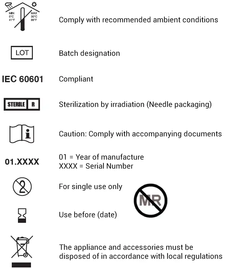
Symbols and Labels
Technical Data
Rx Only
Appliance: Percutaneous Electrical Nerve Field Stimulator (PENFS)
Type description: IB-Stim Stimulator
Power supply: 1 x 3V battery (Type CR1225 Lithium)
Output: Load impedance range 1k ohms-10k Ohms, max. 3.2V, Symmetrical, biphasic stimulation cycles occur at a frequency of 0.125Hz. Max possible total duration of treatment 5x 24 hours.
Protection level: IP20 Type: B
Classification: (in accordance with Directive 93/42 EEC)
Duty type: up to 120 hour duty/ with extended periodic rest.
Weight incl. battery: 5g Dimensions: 36 x 16 x 7 mm
Needle dimensions: 0.5 mm width x 2 mm length
Patents: www.neuraxis.com/about/patents
PN 80011930
LBL011
Rev. No.: 010
A New Standard Of Care
*The IB-Stim is a percutaneous electrical nerve field stimulator (PENFS) system intended to be used in patients 8-21 years of age with functional abdominal pain associated with irritable bowel syndrome (IBS) and functional dyspepsia (FD). The IB-Stim is intended to be used for 120 hours per week, using 1 device per week for 4 consecutive weeks, through application to branches of Cranial Nerves V, VII, IX and X, and the occipital nerves identified by transillumination, as an aid in the reduction of pain when combined with other therapies for IBS and FD. FD patients for whom IB-Stim is indicated have also been shown to experience reduction of nausea symptoms. DEN180057.